Electrolytic tilt sensors are inexpensive passive components that offer unmatched zero stability. Their sensitivity to ambient conditions, however, makes them complex devices that should be understood before installation and operation.
Electrolytic tilt sensors are capable of producing extremely accurate pitch and roll measurements in a variety of applications. They provide excellent repeatability, stability, and accuracy when operating at low frequencies, and come in a variety of packages with varying tilt range and resolution. These rugged, passive devices can be used in environments of extreme temperature, humidity, and shock.
Dual-axis, or 5-pin, sensors can be very cost effective in applications requiring both pitch and roll measurements. Off-the-shelf devices range in price from $5 to $50, and are packaged in cylindrical vials that stand from 0.5 in. to 1 in. high. Operating range of tilt is from ±10°to ±75°, depending on height.
Finding the right electrolytic tilt sensor for your application can be a complicated process. Every application requires a particular set of performance specifications that may or may not be provided by a manufacturer’s off-the-shelf product. With so much at stake–the overall success of your company’s product(s)–your initial evaluation of the sensor prior to design-in should be a top priority.
Narrowing the Field
Prospective electrolytic tilt sensor customers are sometimes left to their own ingenuity to determine exactly what combination of sensor attributes is best for their application. Sensors may vary in height, pin spacing, electrolyte volume and composition, and pin and glass treatment, so there are many possible combinations of attributes for each model of sensor. Recovery from an improper choice is considerably more complicated than screwing in a new light bulb. It can mean changes in board layout, firmware revisions, and different calibration procedures, any of which can cause significant delays in the development or redesign of a product.
To properly evaluate an electrolytic tilt sensor, test its performance in conditions that closely reflect the end product’s actual operating environment. Vendors have signal conditioning boards that can be used to interface the sensor to a host product. Both analog and microprocessor-based modules are offered. The signal conditioning board excites the sensor and provides a linearized analog or digital output to the host. Typically a regulated DC power source is required, and provision is made for offset and gain adjustments. The board must be carefully aligned in order to provide accurate test results.
How Electrolytic Tilt Sensors Work
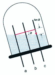
Figure 1. This single-axis view of a five-pin, fluid-filled tilt sensor in the upright position shows the physical relationship among the vial, pins, and fluid when the sensor is slightly tilted.
Figure 1 shows one axis of a fluid-filled sensor tipped at ~15°. As the sensor tilts, the surface of the fluid remains level due to gravity. The fluid is electrically conductive, and the conductivity between the two electrodes is proportional to the length of electrode immersed in the fluid. At the angle shown, for example, the conductivity between pins a and b would be greater than that between b and c. Electrically, the sensor is similar to a potentiometer, with resistance changing in proportion to tilt angle.
But you can’t just attach the sensor to a 6 V battery and expect it to work. The sensor is an electrolytic cell that functions somewhat similarly to a lead acid battery, but in reverse. Instead of converting chemical energy into electricity, a direct electric current induces a chemical reaction–electrolysis–in the fluid. Positive ions in the fluid migrate to the cathode, where they combine with excess electrons and lose some of their charge. Likewise, negative ions in the fluid propagate to the anode and combine with excess protons to lose their charge. If allowed to proceed, the reaction will eventually render the fluid non conductive.
There are a few characteristics of the electrolytic fluid that are important to understand:
• Total conductance varies with both temperature and tilt angle, so a measurement technique that is insensitive to total conductance is required to precisely determine the tilt angle. Sensor manufacturers can control what they call the null impedance at room temperature by changing the volume and chemical composition of the fluid. The extent to which the impedance varies with temperature and tilt depends on the physical properties of the fluid and the geometry of the device. Impedance can typically change by a factor of 20 or more over temperature and tilt.
• The sensor’s angle range is a function of the volume of fluid, electrode spacing, and electrode height. Provided that the electrodes and container are tall enough not to be limiting factors, tilt measurement range is proportional to fluid volume. Because the volume of a liquid is proportional to its temperature, the overall gain, or scale factor, of the device is also proportional to temperature. If this effect is large enough to be significant, the measurement circuitry must compensate by varying gain inversely with temperature.
• The fluid may need to settle after a sudden jolt, so the measurement does not always immediately indicate the sensor’s true attitude. Manufacturers can add damping agents that change the fluid’s viscosity without affecting its conductance, but these work best to filter out high-frequency vibration in an otherwise stable measurement environment. Higher viscosity can also reduce repeatability, especially at high angles, due to interaction between the fluid and its container.
Dual-axis sensors exhibit the same fluid characteristics as single-axis devices–but have the added complexity of interaction between the axes. Both axes share the center electrode. The four outer electrodes are ideally placed at the four corners of a perfect square. Misalignment between electrodes gives rise to cross-axis coupling that can result in significant errors.
There are at least two techniques that can be used to derive independent measurements for each axis. The first is to excite only one axis at a time, alternating between pitch and roll at an appropriate rate. In this case, the excitation must be completely disconnected from one axis while the other is being driven. Leakage to the disconnected side will adversely affect the active measurement.
A second technique requires two excitation frequencies, one twice the other. Here, all four pins are driven simultaneously, and the phase of the excitation determines which axis is being measured. Figure 2 shows the waveforms applied to outer electrode pins a, c, d, and e. Beneath the waveforms, the diagrams indicate the direction of current flow through the sensor.
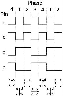
Figure 2. The arrows indicate the direction of current flow that occurs when voltage waveforms apply simultaneous excitation to four outer pins.
Figure 3 shows the major functional elements of a high-end, microprocessor-based, dual-axis tilt meter.
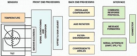
Figure 3. Hardware and firmware functions are performed by a high-end, microprocessor-based, dual-axis inclinometer.
The graph in Figure 4 is an example of a signal vs. tilt angle curve for a sensor excited with 5 V. A plot of the tangent of the tilt angle is also shown for reference. For this sensor, the signal nonlinearity relative to the tangent of the angle is less than ±0.5% for angles below ~20°.

Figure 4. In this sample tilt sensor signal plotted against the ideal tangent response, note that above 20° the signal output becomes nonlinear and requires calibration.
Choosing a Sensor
The primary factors to consider when choosing an electrolytic tilt sensor are:
• Required range of tilt
• Electrolyte impedance and frequency characteristics
• Storage and operating temperature range
Sensor height is determined largely by the required range of tilt. Sensors <0.6 in. high typically have an operating range of less than ±40° tilt. Since range also depends on electrode spacing, you can do a little better by choosing a device with closer spacing, if the option exists. Electrodes are usually spaced on a 0.15 in., 0.2 in., or 0.25 in. dia. circle.
Sensor impedance and frequency characteristics are important in the design of excitation and measurement electronics. The circuitry must accommodate the wide range of impedance presented by the sensor, often a factor of 20 or more. The excitation must be an AC waveform with a frequency high enough to prevent the damaging onset of electrolysis.
Although not usually one of the primary concerns when selecting an electronic device, storage temperature can be crucial to tilt sensors. The mechanical integrity of the seals is essential in preventing electrolyte leakage. Glass and ceramic are popular housing materials because they can be made to produce good, high-temperature seals. Glass has the additional advantage of transparency, allowing the level and color of the electrolyte to be observed.
The operating temperature range determines the extent to which the measurement circuit must compensate for impedance and scale factor change. For many electrolytes, if the operating range is limited, the scale factor change due to electrolyte expansion and contraction can be ignored. If you are attempting to use a sensor near its maximum tilt angle, the operating temperature range may need to be limited due to temperature dependence of the nonlinear signal transfer characteristic in this region.
Proper Calibration
In many applications, absolute tilt angles in degrees, radians, mils, or fractions of a revolution are not needed. It may be sufficient to normalize the raw measurement signals from the sensor to compensate for offset and gain variation, in which case the resulting signals are proportional to the tangents of the angles. Your measurements may be repeatable for a single unit, but there may still be unit-to-unit variation due to uncompensated cross-axis coupling. If you’re looking for unit-to-unit repeatability of better than 1° or 2° over a range of more than ±10° to ±15° of tilt, you probably need to calibrate in order to compensate for cross-axis coupling.
Summary
If you need to measure tilt, electrolytic tilt sensors are an excellent choice. Their advantages are low cost, low power consumption, repeatability, and reliability. However, they are complex devices due to their sensitivity to both internal (circuitry) and external (environmental) influences, which can alter their performance. Users unfamiliar with the technology would be well advised to work closely with vendors or consultants who can guide them through the evaluation process.
Receive A Free Quote